Getting Started
Minimum setup
To start developing with the M.2 M-key Stack FMC, we recommend that you get setup with the minimum hardware and software requirements:
- An FPGA or MPSoC development board from our list of supported boards.
- One M.2 M-key Stack FMC.
- At least one M.2 NVMe SSD (see our list of tested SSDs).
- Build and run one of our example designs.
Hardware setup
For instructions on attaching the SSDs and connecting the M.2 M-key Stack FMC into the carrier board, we have put together the following video:
Fastening the mezzanine
FMC mezzanine cards are not hot-pluggable; to prevent the mezzanine card from detaching from the carrier while active, we recommend using the provided machine screws to fix the mezzanine card to the carrier board. The screws should be screwed into the mezzanine’s hex standoffs from the underside of the carrier board. The details on these screws can be found in the mechanical information section.
Attaching a second FMC
To attach a second FMC to the M.2 M-key Stack FMC:
- Remove the pre-assembled hex standoffs and screws from the M.2 M-key Stack FMC
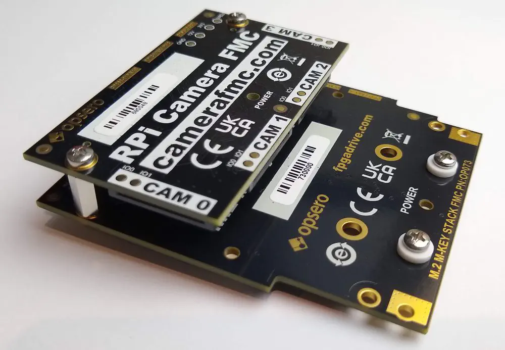
- Flip the board over so that the M.2 connectors are facing down. Connect the second FMC to the M.2 M-key Stack FMC by plugging it into the carrier-side FMC connector. In the example shown below, we have attached the RPi Camera FMC.
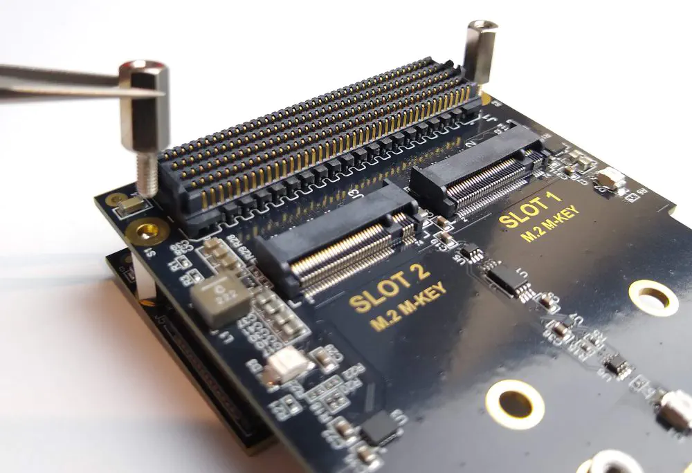
- Flip the board over again so that the M.2 connectors are facing upwards. Screw the provided V6622C standoffs into the standoffs of the second FMC, through the mounting holes of the M.2 M-key Stack FMC
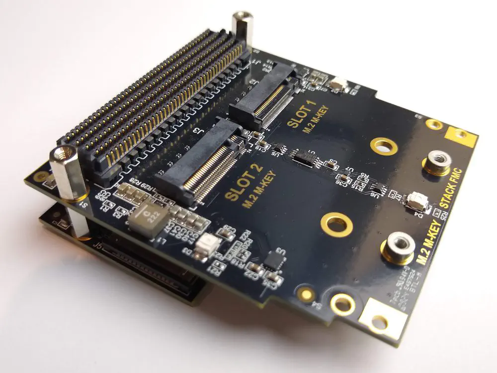
The resulting stacked FMC should look like the image below:
Clearance from M.2 standoff hardware
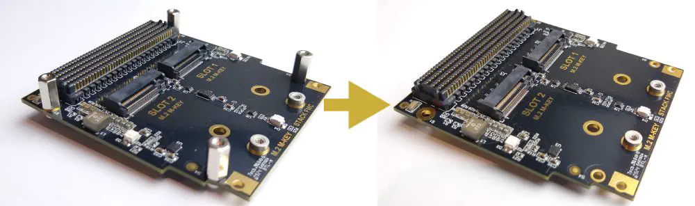
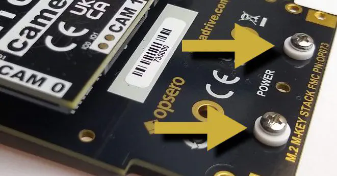
The M.2 M-key Stack FMC comes pre-assembled with 2x round M.2 standoffs that are fixed to the board with machine screws and white nylon spacers. This method for fixing the M.2 spacers to the board allows the position of the spacers to be easily changed to suit the M.2 modules being used. The screws and nylon spacers are highlighted in the image below.
Some mezzanine cards, when used as the second FMC, may not have sufficient clearance from the screws and nylon spacers holding the M.2 standoffs. When using such mezzanine cards, remove the screws and nylon spacers and instead attach the M.2 standoffs by soldering them or gluing them with a conductive epoxy. Before gluing or soldering, be sure to use the correct mounting holes to suit your M.2 modules.
Software setup
In order to build our example designs, you will need to setup your PC with the AMD Xilinx development tools:
The Vivado and Vitis tools support most operating systems, whereas the PetaLinux tools can only be installed under Linux.
For the specific versions required, please refer to the release notes in the Git repository of the particular example design you wish to build.