Title here
Summary here
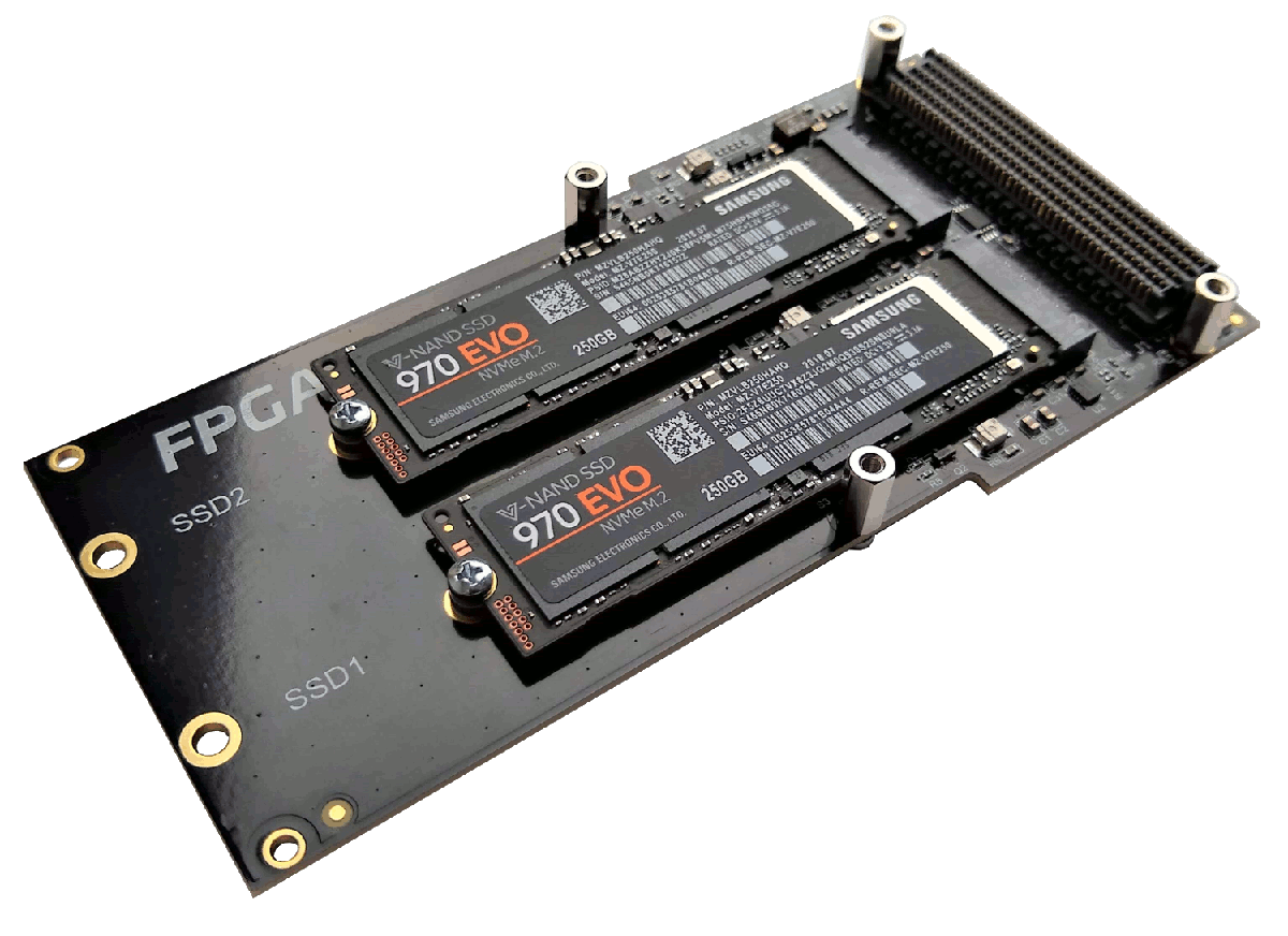
PCIe SSDs interface with the PCIe blocks integrated into your FPGA, so there is no need for expensive SAS and SATA IP.
The 4-lane PCIe interface has a higher bandwidth than SATA and the NVMe protocol stack has much lower latency.
All major Linux distributions have NVMe driver in-box support (including PetaLinux).
Fully functional example designs you can download on Github and try now.
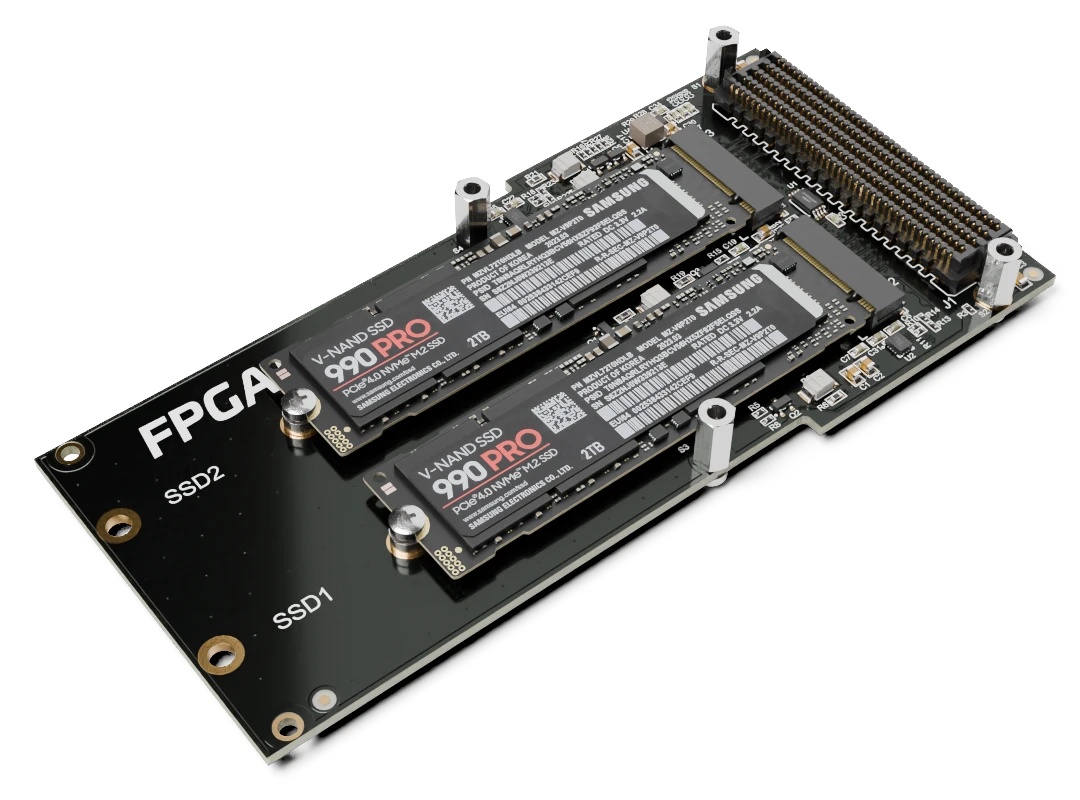
NVMe Solid-state drive connectivity for FPGAs and SoCs
Find out more